Shinyei PPD42NS dust sensor

Stuttgart, the city I live in, is on first place for most particles in the city. But there is only one sensor in the city to measure the particles.

As OK Lab Stuttgart we want to get open data from the city or acquire our own data. In this case we want more data points for particles. And not only at one position in the city, but on as many as possible.

We decided to try the PPD42NS. Other projects used the PPD42NS before:

The datasheet of the PPD42NS from the shinyei website: http://www.sca-shinyei.com/pdf/PPD42NS.pdf. And some kind of deconstruction how the sensor works: http://takingspace.org/wp-content/uploads/ShinyeiPPD42NS_Deconstruction_TracyAllen.pdf

There are a few examples how the sensor is used with Arduino, i.e. http://www.seeedstudio.com/wiki/Grove_-_Dust_Sensor#Usage or https://github.com/Seeed-Studio/Grove_Dust_Sensor.

The arduino is not cheap enough to build lots of them and distribute them. And wifi is missing (or too expensive). So we decided to try the ESP8266 which is widely used in the hacker community at the moment.

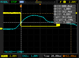
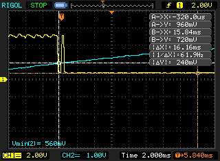
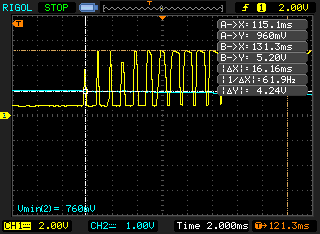
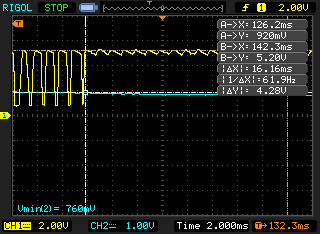
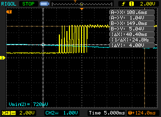
Our sourcecode is at https://github.com/opendata-stuttgart/sensors-software/tree/master/esp8266/ppd42ns. But this is work in progress. The esp8266 is a lot faster than an arduino, so we have problems with very short peaks in the digital output of the sensor and need to smooth the signal. To illustrate the problem we made a few pictures with a digital oscilloscope:

ppd42ns oszilloscope imageppd42ns oszilloscope imageppd42ns oszilloscope imageppd42ns oszilloscope imageppd42ns oszilloscope image

Voltage Regulator

To use the ESP8266 and the PPD42NS together we need 5V and 3.3V.

There are some ways to achieve this.

First option

Buy a LM1117.

Second option

I didn't have a LM1117, but got a LM317 and two resistors.

The schema to build a voltage regulator with this is:

schema

The source of the image is in https://github.com/opendata-stuttgart/sensors-software/blob/master/schematics/voltage-divider.fzz

Important: The LM317 pins are not as expected! The ADJ is the left pin. For reference see: http://www.st.com/web/en/resource/technical/document/datasheet/CD00000455.pdf

Test the voltage

Using the Arduino it's really easy to measure the voltage. The program is:

void setup() {
  Serial.begin(9600);
}

void loop() {
  Serial.println(analogRead(A0) * (5.0 / 1023.0));
  delay(1000);
}

The resulting voltage should be around 3.16V.

First steps with the ESP8266

The first steps are with an ESP8266-01.

Step 1

Connect via a FTDI to the usb of your PC. I'm using FTDI Basic Program Downloader USB to TTL FT232 and Ubuntu 14.04.

Pin layout

see http://playground.boxtec.ch/doku.php/wireless/esp8266

Now map your ftdi pins to the esp8266 pins like this:

ESP

<->

FTDI

RX

TX

TX

RX

CH_PD

3.3V

GPIO 0

GND

VCC

3.3V

GND

GND

Step 2

Clone https://github.com/themadinventor/esptool

and run esptool flash_id to see if everything works.

The output for my unflashed esp8266 was:

Manufacturer: c8
Device: 4013

Step 3

Get your new firmware to flash on your esp8266. For example the nodemcu one: https://github.com/nodemcu/nodemcu-firmware/tree/master/pre_build/latest

And now flash it:

sudo python esptool.py write_flash 0x00000 nodemcu_latest.bin

Step 4

Before using the esp8266, the remove GPIO from GND!!

Test with a simple wifi connection in Lua.

One way to upload your lua code is https://github.com/4refr0nt/luatool .

Another quite easy way with GUI is http://esp8266.ru/esplorer/